Surge protection for systems in power plants
Method and arrangement for surge protection
Method and arrangement for surge protection
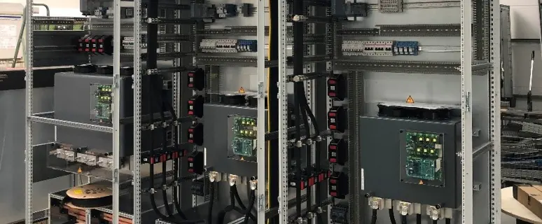
The following report describes surge protection devices (SPD) used in a Vattenfall thermal power plant.
The term overvoltage refers to short-term voltage increases up to 1.4 times the rated voltage, which pose a risk to downstream electrical components and can, for example, occur due to generator voltage oscillations during load shedding or a transition from grid operation to island operation.
Such overvoltages exceed the overvoltage disturbance limits of power electronic and/or electronic modules installed in the power plant.
These overvoltages act over a period of time that can last up to several seconds.
With the increasing volatility of supply networks, which can occur for example due to the growing use of renewable energies, this issue is gaining in importance.
The mentioned power electronic modules, such as frequency converters, typically supply large pump systems in thermal power plants, which regulate the transport of hot and cold water. Such pump systems must not be relieved suddenly in the medium and high load range, as this could cause pressure surges in the piping system. These pressure surges must be avoided, as they endanger the proper operation of systems in the thermal power plant and can lead to the destruction of pipelines.
As a result, a complete failure of the affected thermal power plant is possible, which could lead to gaps in the supply to industry, commerce, and private households.
Solution approach:
In each phase, a bidirectional thyristor power switch and a damping resistor arranged in parallel are installed.
The control signals for the anti-parallel connected thyristors in each phase are provided depending on the load current and the current mains voltage according to a predefined switching characteristic curve.
The optimal time to block/trigger the thyristors and thus switch on the damping resistors upon detection of an overvoltage is determined based on the mains voltage, the mains current, the overvoltage control limit, and the overvoltage disturbance limit of the consumer.
The formation of the switching characteristic curves is carried out in such a way that the switching point shifts to higher voltages according to a control characteristic curve, depending on the load current.
